A few years ago, I wrote a blog called “How to Design a Basic Overdrive Circuit.” This blog has been one of our most popular posts ever! Recently, I’ve wanted to do a part 2, but this time focusing on a basic distortion circuit.
Even though overdrives and distortion circuits have similarities, the approach is often quite different. And, there isn’t just “one” way to design any pedal—whether it’s an overdrive or distortion pedal. However, I’m quite certain we can make a great-sounding distortion pedal with a minimal parts count.
And, I’m not going to do any math manually. I like to play guitar into pedals when designing; I’m not a big fan of designing from the point of view of algebra equations, oscilloscopes, and signal generators. Those things come in handy, but first and foremost, I’m a guitar player. I started building guitar pedals so I could create pedals for myself, to inspire creativity, get some great sounds, and most importantly—to have fun.
While I’m going to try to write this in a way that’s as easy to understand as possible, I realize some folks might have a hard time grasping some terms. For example, you may not know a MOSFET from a Boba Fett, or a feedback loop from a Froot Loop, and that’s okay. I’ll keep this as ELI5 as possible. And if you like this kind of stuff and want to learn more, head over to my other website, https://www.guitarpedalcourse.com, and check out my beginner’s guide to designing pedals. It’s one of the few online courses completely tailored to those with no electronics experience.
Let’s face it—it’s always possible to learn for free on the internet, but if you’ve been online for the past few years, you know that asking basic questions on forums tends to rile up some group and forum members, and ends up being less than helpful for whatever reason. It definitely is the cheaper route, just not the quickest.
With that said, let’s dive in!
Part I – The Basics…
Last time, we started with a simple op-amp-based overdrive with soft clipping and a basic tone control. What if we take that same principle and apply it to distortion? Well, let’s see!
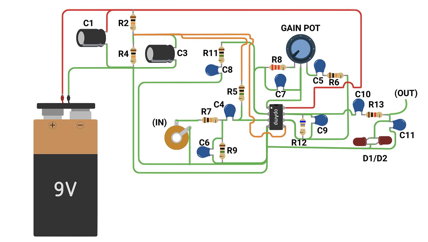
That circuit block will look like this:


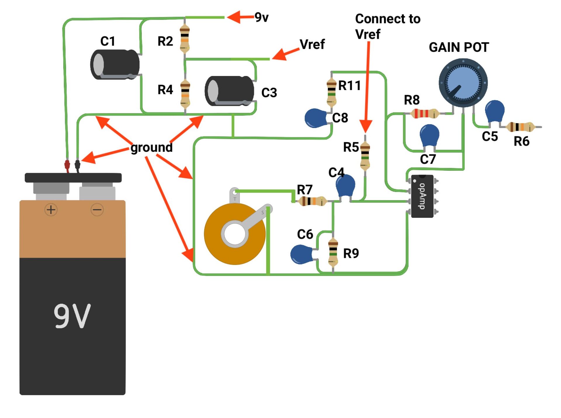
What does all that mean? Well, a battery is pretty self-explanatory—we need power. Batteries are the most basic way to get power into a pedal. We want to keep it as quiet as possible, and even though batteries generally don’t have noise problems, C1 will help us keep some stray noise down.
BUT—our circuit needs to be biased. Using a battery like this, we need a “virtual ground,” or a midpoint between 9 volts DC and ground (0 volts). So, we will use a voltage divider consisting of two equal-value resistors and a capacitor. I’m using 10k resistors here: one connected to the 9V positive terminal and the other to ground, connected in series. The midpoint is approximately half of the 9 volts that the battery provides. We also need a large capacitor here to help stabilize this “virtual ground,” which is what C3 is for. We’ll call this “Vref,” short for “Voltage Reference.”
Part II – the Fun Stuff
Now, with that out of the way, let’s focus on the fun stuff! First, we need to get the guitar signal into the audio portion of the circuit. What better way to do that than with a guitar jack? We will use a mono jack to simplify things—so the only connections will be the signal positive (the signal from the guitar) and ground. You see, all these grounds essentially get tied together, and without ground, our circuit simply won’t work. You gotta have the yin and the yang, the sun and the rain, as they say. I’m not sure who says that, but surely someone does.
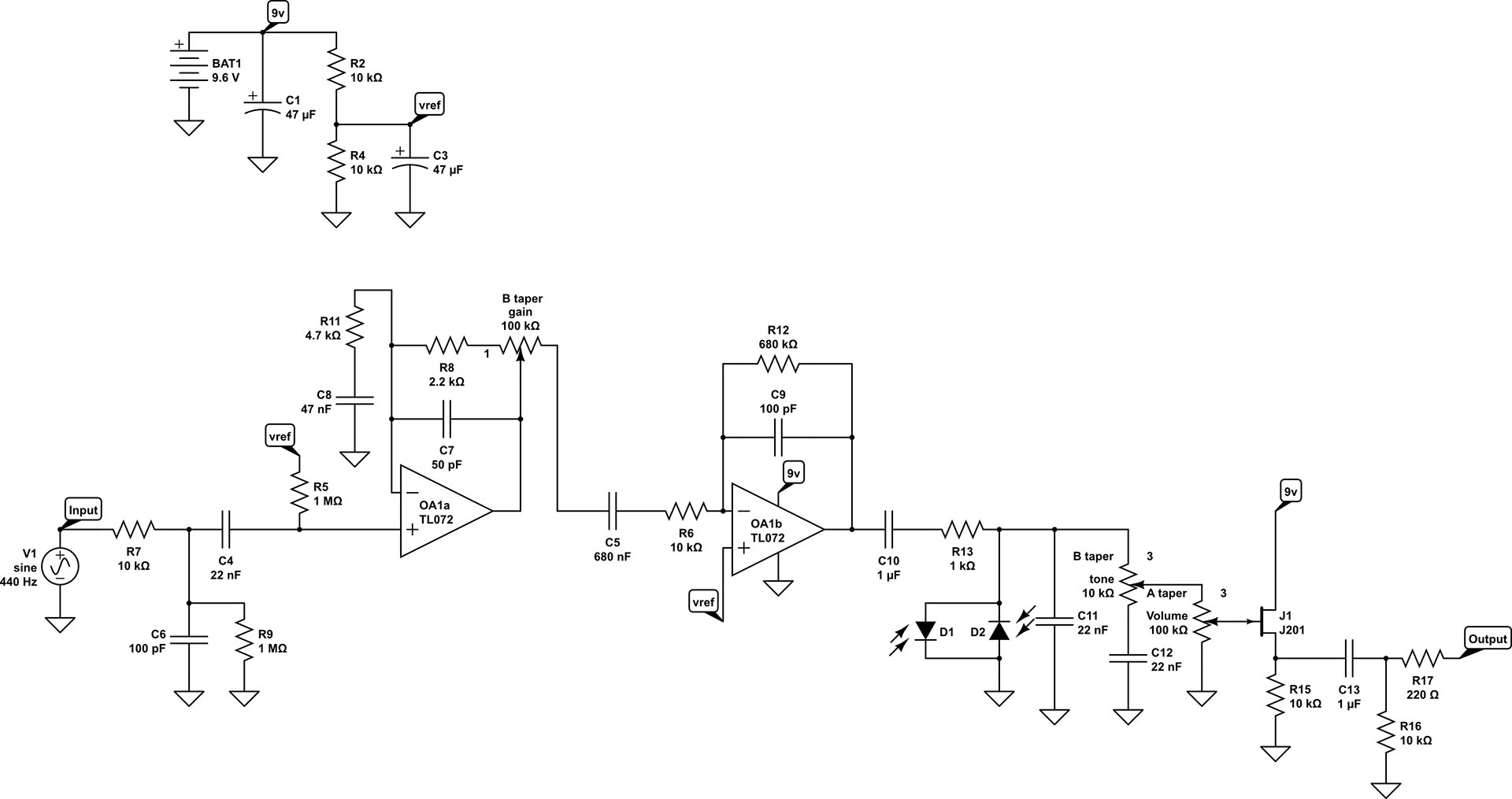
So, this jack’s positive lug—the one carrying the guitar signal—will connect to the input of our first gain stage. We’re going to connect this jack to R7, a resistor, then to C4, an input capacitor, and then to the first op-amp. However, we need a few other things here. Between R7 and C4, there is a resistor and capacitor going to ground. What are these for? Well, C6 and R7 form what’s called a low-pass filter, which removes some very high frequencies. Is this absolutely necessary? Nah, not really, but it’s good practice and can help with noise a bit, mainly filtering out radio frequencies that might come through. It’s kind of like wearing a seatbelt—good practice, doesn’t hurt anything, no downside really. R9 isn’t absolutely necessary either, but if we connect this to an on/off switch, it helps with the POP! you sometimes hear when turning a pedal on or off. R5 simply connects to Vref—this biases the op-amp and essentially makes it work.
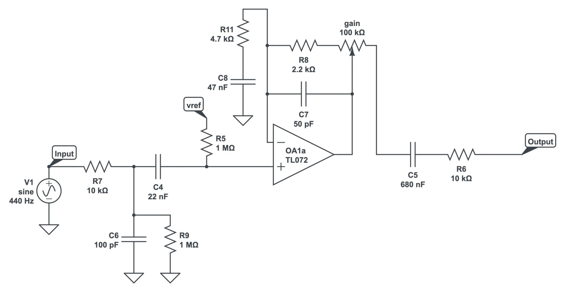
The signal goes into that triangle-shaped thingy, which schematically means it’s an op-amp. The black IC chip we are using has two of these op-amps in it, and therefore the chips themselves are referred to as “dual op-amps.” This first stage is going to be a non-inverting gain stage. It’s called a non-inverting stage because the signal does not invert and goes into the positive input pin. This is a pretty standard op-amp style gain stage, with R8, the gain pot (a 100k here), R11, and C8 all dictating how much gain this portion of the circuit will put out and the frequencies of the gain. C7 takes off some very high frequencies, and we generally use this to help keep this gain stage stable. If you make this capacitor bigger, you’ll just cut off more and more highs, so we’re keeping this at around 50pf.
R8 is our “gain limiting” resistor, meaning when the gain pot is turned down, there’s still a little bit of gain. Making this resistor smaller or larger will help determine how much gain is present with the gain control all the way down.
Let’s pause for a minute and discuss a few terms. Often when we guitarists think of “gain,” we think of distortion. In reality, gain can be more analogous to volume in a way—the more gain, the louder the circuit will be up to a point where the circuit physically can’t increase the volume. When this happens, the circuit “clips”—clipping meaning distortion. With that said, keep in mind that as we discuss gain, it does not necessarily mean “distortion,” it just means we’re boosting the input signal louder, to explain it simply.
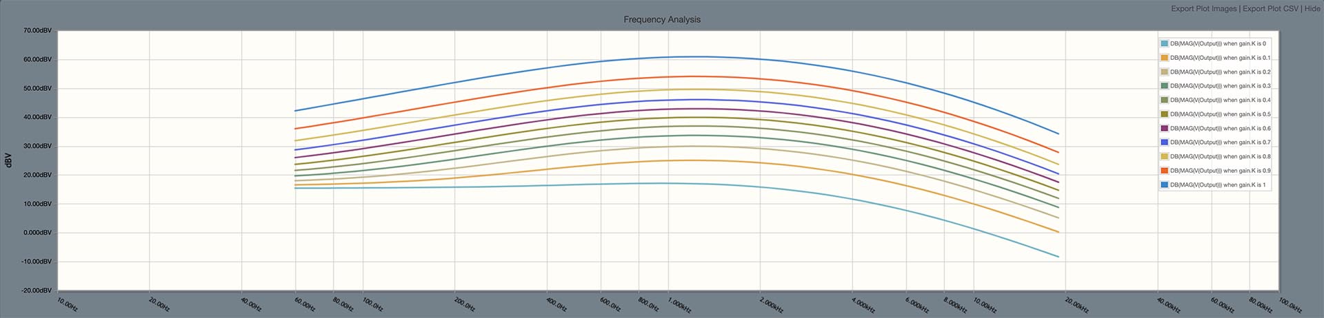
As we turn the gain from minimum to maximum in 10% increments, here’s what the frequency plot looks like so far:

You’ll notice some bass roll-off—this is mainly due to the ratio of R11 and C8. For more bass, increase C8. For less bass, decrease C8.
Now let’s follow the signal path as it exits this non-inverting op-amp. We’ll go through C5 and then R6 before hitting the next stage. I’ll explain in a minute how C5 and R6 are actually part of the next gain stage as well.
Now that we have a gain control, we need to add another gain stage, some clipping diodes, and a bit more filtering of the frequencies.
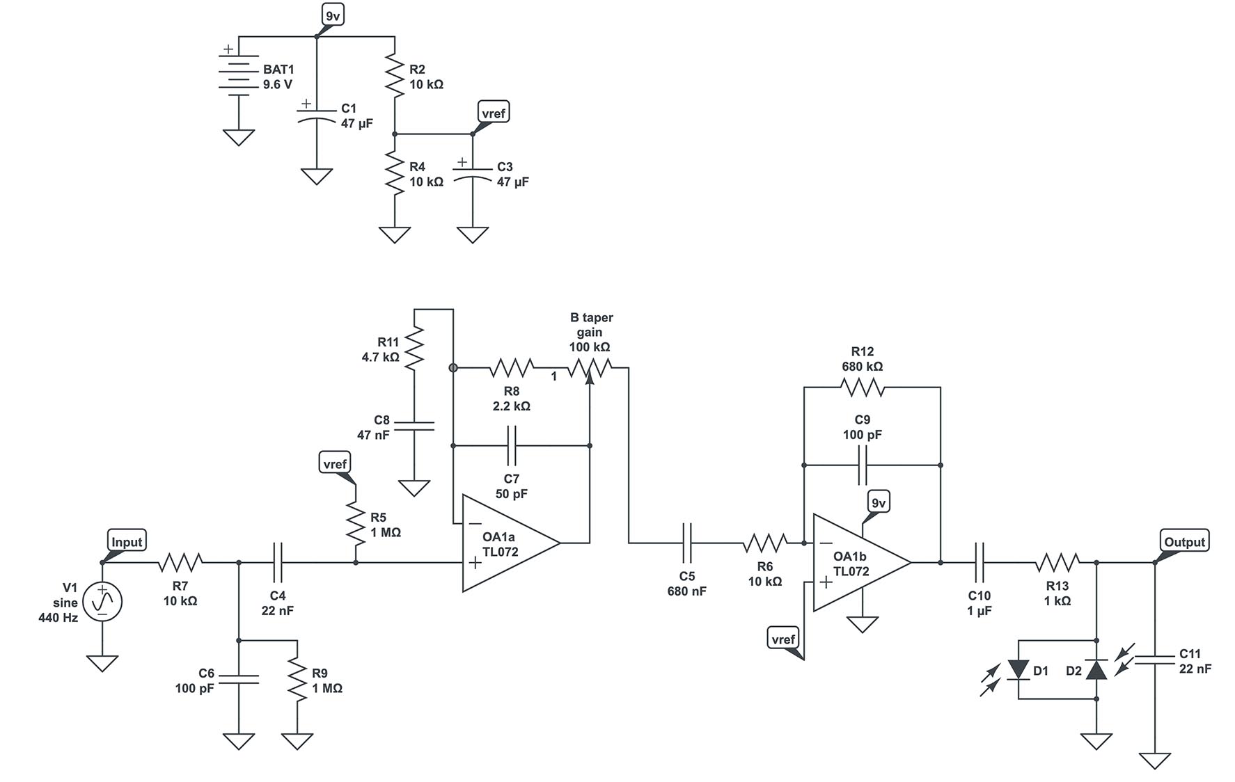
First, let’s add an inverting op-amp rather than a non-inverting one. Why? Because we’re working on something that looks a bit closer to a MI Audio Crunchbox, JHS Angry Charlie, Suhr Riot, and many other distortion circuits. To do this, our signal will go from R6 into the negative, or more correctly, the inverting input pin, designated by the minus sign. In this stage, R12 controls the gain, and C9 takes off a bit of the highs again (similar to what we found in the previous non-inverting op-amp stage, where R8 and the gain control dictated how much gain was in the circuit). But wait, why isn’t there a resistor and capacitor to ground?
Well, in this type of gain stage, C5 and R6 do a job similar to what R11 and C8 did in the non-inverting op-amp stage—they control gain as well as the frequencies being boosted. Also, being an inverting op-amp, we need to connect the non-inverting input pin, designated by the plus sign, directly to Vref (Virtual Ground). This is because we’re using a unipolar power supply—a battery. For the sake of this blog, consider Vref as a “make-believe ground” to make the circuit operate properly. Again, making C5 larger will add more bass to this stage, and vice versa.
Now it’s time to exit this op-amp and do some signal clipping. In actuality, with this 9V circuit, we’ve already exceeded the op-amps’ ability to cleanly boost the volume, so it’s going to be a bit distorted as you turn the gain up. Our signal will exit from the IC chip’s second op-amp output pin, go through C10 and R13 before connecting to clipping diodes and a capacitor to ground. I’m using LEDs as clipping diodes here because they provide a bit less compression, as they don’t clip as much as standard diodes. C11 combined with R13 form a low-pass filter, taking off the highs. In this stage, you could swap out the diodes for your favorites and make C11 larger if you want to reduce the shrill “raspiness” of the diodes hard-clipping the circuit, or smaller if you want to take off fewer highs.
There are often multiple ways to make these types of changes, but I don’t want to get off into the weeds too much. For example, we could change R13 to a different size resistor to alter the high-end frequency filtering here, but that creates a different issue—our clipping doesn’t react the same. All of that to say, experiment! It’s often a lot of fun just plugging in different values and seeing what happens.
From here, let’s look at what the signal looks like so far:
That’s a nicely rounded frequency plot so far! Let’s keep going!
Let’s add a simple passive tone control and a volume control now. Our tone control, a 10k linear potentiometer, connects lug 3 to the signal and lug 1 to a capacitor, C12, which connects to ground. This means that as you turn the tone control down, more and more high frequencies are being sent to ground, reducing the high frequencies in the output. This type of tone control is similar to what you find on pedals like the Boss BD-2 Blues Driver and the Boss OD-3 Overdrive. Our signal will exit this tone control through lug 2 and go into the volume control—standard stuff here. It’s technically just a “variable voltage divider,” but we use it for controlling volume more often than not.
Let’s see what it looks like with the gain set at noon, and turning the tone control in 10% increments from minimum to maximum:
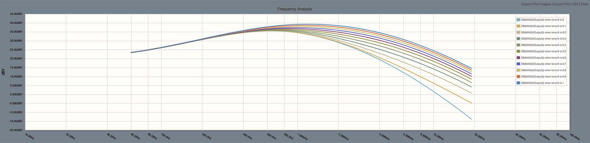
You might be saying to yourself, “But it looks like a big mid hump—why are we getting rid of so many high frequencies?!” The answer is that clipping and distortion cause a lot of harmonics. Those harmonics sound to the ear like a raspy, sizzly, ear-piercing, ice-picky mess. Ultimately, we want to try to get noon on the tone control to be a sweet spot if possible. It doesn’t always work out this way, but combining the low-pass filtering of R13/C11 along with the tone control should get us close-ish. Really, though, you almost always want some amount of highs taken off; it often sounds terrible without doing that. You can make C12 a larger value capacitor as well, but this changes the overall EQ of the circuit, often giving it the sound of fewer mids and a bit more raspy highs. But hey, you might like that! It certainly won’t hurt to give that a spin on the ol’ breadboard.
So that’s the circuit, folks! You might wonder where to get a breadboard and supplies. There are a variety of places that sell parts tailored for the guitar pedal builder. A popular place is here: https://smallbear-electronics.mybigcommerce.com/
I also have one of my secondary websites set up to breadboards and parts for breadboarding that you can buy from Amazon as well, here: https://wamplerdiy.com/collections/diy-pedal-parts

I hope this helped you understand the basic of how these types of circuits function, and how by using a breadboard we’re able to quickly and efficiently design a circuit, and play through it, now go out there and experiment and create something cool!


Love it I see some changes I’d do not that they’re better just more up my alley